Can I run dex6 in my th400.

Status
Not open for further replies.
I got the pump all put back together with new gears and I got the pump cover surface gap fixed so the two halves went together flat. I bought the sonnax no walk rear case bushing 34006-os. Can I still use the th350 front pump Torrington bearing with this rear bushing if i want to rollerize the rear?
 
Last edited:
Originally Posted By: joegreen
I got the pump all put back together with new gears and I got the pump cover surface gap fixed so the two halves went together flat. I bought the sonnax no walk rear case bushing 34006-os. Can I still use the th350 front pump Torrington bearing with this rear bushing if i want to rollerize the rear?


No, The Sonnax bushing has a lip on it that makes it to large for the bearing to slip over it.
 
Clinebarger, thank-you for sharing such good tech info! I'm on the fence with dual feeding a 4L80 in a pickup and have a few question if I may:

Originally Posted By: clinebarger
The slower reverse apply is my biggest concern, Just be patient & let it latch up before applying throttle.

What's the ball-park for how much slower? Are we talking a partial second, or could it be two or three seconds? Does leaving out the Reverse check ball help with this?

Originally Posted By: clinebarger
During full throttle 3-1 & 3-2 automatic/forced downshifts, The direct piston return springs are not strong enough to return the piston in a timely manner because it's trying evacuate 200% more ATF than the circuit was designed to evacuate, Over time this WILL distress the direct frictions.
I HIGHLY recommend "High Rate" return springs in any dual feed hydramatic transmission.

Do the stiffer springs FIX the issue or just reduce the release drag to a semi-tolerable level? I saw elsewhere (from you?) that removing the seal lands, in addition to the seal, from the center support can help speed release?

Originally Posted By: clinebarger
Dual Feeding the directs is a fantastic modification.......On rigs making north of 450 horsepower!! I rarely do this mod on a heavy duty unit, It is just not warranted.

Below that currently at about 385, but the future could add some to that. . .

My apologies to joegreen if I'm sidetracking too much!
 
Originally Posted By: clinebarger
Originally Posted By: joegreen
I got the pump all put back together with new gears and I got the pump cover surface gap fixed so the two halves went together flat. I bought the sonnax no walk rear case bushing 34006-os. Can I still use the th350 front pump Torrington bearing with this rear bushing if i want to rollerize the rear?


No, The Sonnax bushing has a lip on it that makes it to large for the bearing to slip over it.

Thanks
 
Originally Posted By: JiL
Clinebarger, thank-you for sharing such good tech info! I'm on the fence with dual feeding a 4L80 in a pickup and have a few question if I may:

Originally Posted By: clinebarger
The slower reverse apply is my biggest concern, Just be patient & let it latch up before applying throttle.

What's the ball-park for how much slower? Are we talking a partial second, or could it be two or three seconds? Does leaving out the Reverse check ball help with this?

Originally Posted By: clinebarger
During full throttle 3-1 & 3-2 automatic/forced downshifts, The direct piston return springs are not strong enough to return the piston in a timely manner because it's trying evacuate 200% more ATF than the circuit was designed to evacuate, Over time this WILL distress the direct frictions.
I HIGHLY recommend "High Rate" return springs in any dual feed hydramatic transmission.

Do the stiffer springs FIX the issue or just reduce the release drag to a semi-tolerable level? I saw elsewhere (from you?) that removing the seal lands, in addition to the seal, from the center support can help speed release?

Originally Posted By: clinebarger
Dual Feeding the directs is a fantastic modification.......On rigs making north of 450 horsepower!! I rarely do this mod on a heavy duty unit, It is just not warranted.

Below that currently at about 385, but the future could add some to that. . .

My apologies to joegreen if I'm sidetracking too much!
no probs. Feel free to ask whatever questions you want.
 
Originally Posted By: JiL
Clinebarger, thank-you for sharing such good tech info! I'm on the fence with dual feeding a 4L80 in a pickup and have a few question if I may:

Originally Posted By: clinebarger
The slower reverse apply is my biggest concern, Just be patient & let it latch up before applying throttle.

What's the ball-park for how much slower? Are we talking a partial second, or could it be two or three seconds? Does leaving out the Reverse check ball help with this?

Originally Posted By: clinebarger
During full throttle 3-1 & 3-2 automatic/forced downshifts, The direct piston return springs are not strong enough to return the piston in a timely manner because it's trying evacuate 200% more ATF than the circuit was designed to evacuate, Over time this WILL distress the direct frictions.
I HIGHLY recommend "High Rate" return springs in any dual feed hydramatic transmission.

Do the stiffer springs FIX the issue or just reduce the release drag to a semi-tolerable level? I saw elsewhere (from you?) that removing the seal lands, in addition to the seal, from the center support can help speed release?

Originally Posted By: clinebarger
Dual Feeding the directs is a fantastic modification.......On rigs making north of 450 horsepower!! I rarely do this mod on a heavy duty unit, It is just not warranted.

Below that currently at about 385, but the future could add some to that. . .

My apologies to joegreen if I'm sidetracking too much!


1st question. Reverse "Latch-up" time varies by what Pressure Regulator Spring, Boost Valve, & Orifice sizes in the Separator Plate are used, The delay is small in most cases(10th's of a second over what it was). But on a plow truck, Work trucks that back trailers often, A truck that gets stuck in the mud/ice often, Or just an impatient driver CAN damage/distress the Direct frictions......Because these operators never cared in the first place how long it took, The only reason I made that statement was because I thought Joe's truck was dedicated to plowing.
YES, Removing the #9 checkball will dramatically reduce latch-up times, At the same time Reverse will become VERY harsh.....Not good on the drive splines on the Direct frictions, Direct Drum to Sun-Gear shaft splines, U-joints & Really bad on the Transfer Case if equipped.
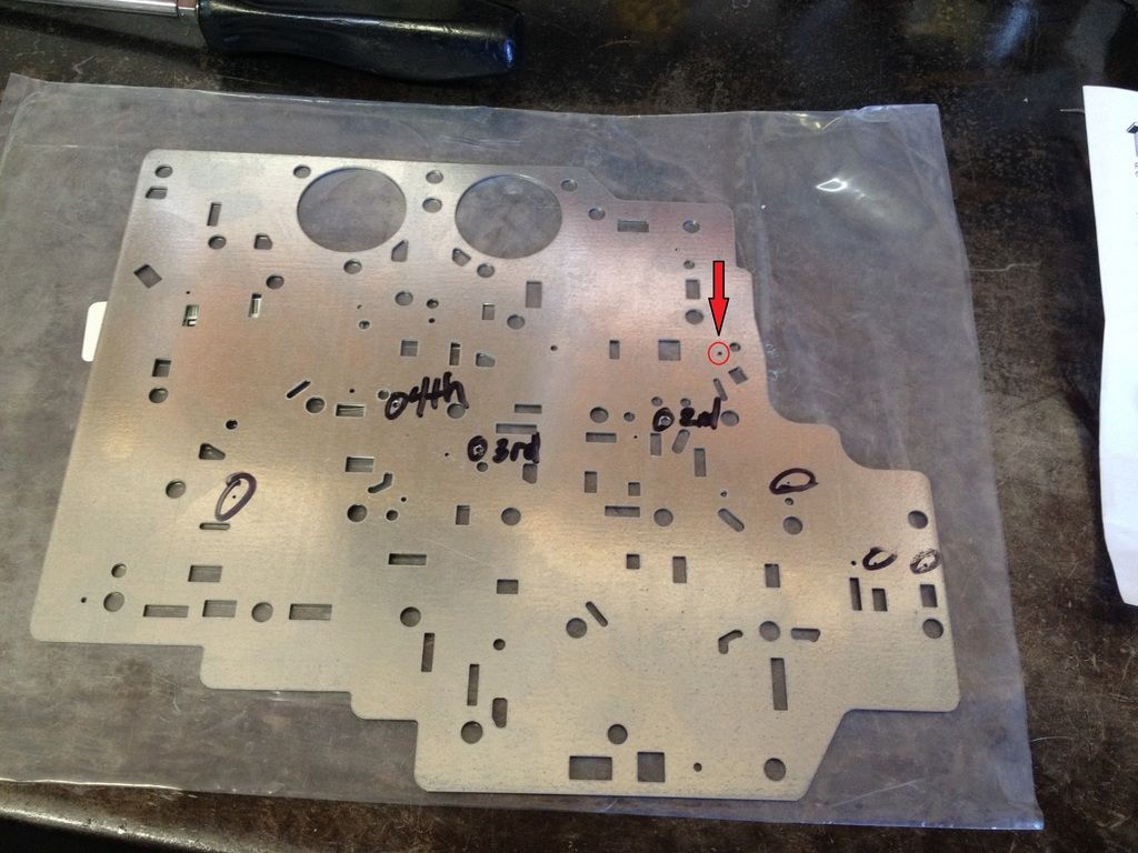
If you want to do a modification to quicken the circuit apply.....Increase the size of the orifice feeding Direct clutches in reverse (Red Circle) by 20%.

2nd question. The springs help many high rpm issues with the Direct Clutch, Quicker release & prevents "Centrifugal Piston Creep" in lower gears.
Face Grooved frictions also help with friction to steel separation & Oiling of the friction faces when the frictions are overrunning.
I remove the center lip seal in the Drum & Omit the second sealing ring on the center support on every dual feed TH400/4L80E. Machining the unused ring lands off the Center Support increases flow rates during apply & release.

 
Last edited:
Perhaps some clarification (for JiL) is in order on your comment about increasing the orifice size by 20%. Do you mean to say increase the area of the orifice by 20% or the diameter by 20%? There can be huge difference between them and not everybody realizes that.

For those who don't know, depending on the beginning diameter, an increase of a few to several thousandths of an inch can increase an orifice's area by 20% or more. Just trying to save some potential head scratching!
 
Thanks much for posting, I really appreciate the input and information.

I think I could tolerate that small of an increase in Reverse lock-up.

I'm assuming the 20% is a change in area.
 
I've come across the suggestion to restrict the Forward to Intermediate bleed-in orifice by 30% or so, but its location wasn't given and I haven't been able to pin it down from the ATSG book. Any experience with this?
 
Originally Posted By: JiL
I've come across the suggestion to restrict the Forward to Intermediate bleed-in orifice by 30% or so, but its location wasn't given and I haven't been able to pin it down from the ATSG book. Any experience with this?


The way I read that is......"Forward to Intermediate" Means 1st to 2nd gear.....So I guess they are speaking of the Intermediate Clutch Apply Orifice?
I would like to know the context surrounding this advice? To big a 2nd Clutch feed orifice is HARD on the Intermediate Sprag/Roller Clutch. With a Post '97 34 Element Sprag & Direct Drum....A .125" orifice in a light car with a loose converter is safe, In a 2500/3500 truck that hauls at max GCWR, .086" is the absolute limit.
 
Originally Posted By: JiL
These are two of the comments: (clicking in the top right of the single post should show the full thread)
http://www.yellowbullet.com/forum/showpost.php?p=10662777&postcount=11

http://www.yellowbullet.com/forum/showpost.php?p=10339102&postcount=27


OK, I understand now. Varying nomenclature can be confusing, Drive Oil is priming the 2nd/Intermediate clutch apply circuit, This was done to keep 1-2 shift times to a minimum.

No issues with blocking it or reducing orifice area IF the PCM is tuned for it, The engine may hit the rev-limiter before the 1-2 shift can be completed at WOT, You may have to lower the MPH & RPM for the 1-2 shift.

The 2nd Clutch circuit is pretty big when you take in account the Accumulator, Case passage, & the Center Support that has a bleed orifice, Also the 1-2 shift valve is exhausting the 2nd Clutch circuit in 1st gear.

We have to take into account WHAT/WHO'S separator plate your going to use in your build? Also.....What PR Spring & Boost Valve is going to be used? Are you going to use "high rate" Intermediate Piston return springs? The last thing you want to do is Over modify your transmission by using fragments of information.


Chris @ CK Performance (chris718) is well respected in the transmission community, This is could be outdated information as HIS current separator plates have the "Bleed-In" orifice! Albeit it looks smaller than a stock plate. I have a Stock plate, A Trans-Go (Replacement & HD2) plate, & a CK plate.....I will post the Drive Oil to 2nd Clutch orifice sizes later.

The Separator Plate information is most likely in your ATSG manual but does not provide good/clear Hydraulic Diagrams to guide you.

A look at the hydraulic diagram shows that Drive oil (Forward Clutch Oil) passes through the plate, Loop's through a passage in the Valve Body & discharges through a restricted orifice in the plate to the 2nd Clutch circuit. Shown in-line, Red arrow pointing at the restricted orifice.

 
This tells us that Drive Oil & the 2nd Clutch circuit meet in the plate somewhere, Drive oil is 19, And 2nd Clutch is 24. Just look for the combined circuit 19/24...This your "Bleed-In" orifice.

 
Originally Posted By: clinebarger
No issues with blocking it or reducing orifice area IF the PCM is tuned for it, The engine may hit the rev-limiter before the 1-2 shift can be completed at WOT, You may have to lower the MPH & RPM for the 1-2 shift.

Thanks for the tip on what to expect. Should be able to make the proper adjustments.
Originally Posted By: clinebarger
We have to take into account WHAT/WHO'S separator plate your going to use in your build?

ACDelco to replace the check-ball damaged and rusty(?) original.
Originally Posted By: clinebarger
Also.....What PR Spring & Boost Valve is going to be used?

I have a Shift Technology shift kit. Don't really know if it's a good one to go with or not. Couldn't really find much info.
Originally Posted By: clinebarger
Are you going to use "high rate" Intermediate Piston return springs?

Hadn't decided. Input?
Originally Posted By: clinebarger
The last thing you want to do is Over modify your transmission by using fragments of information.

"Fragments of Information." That is how it has felt trying to piece together a little here and a little there. When someone says, "Do this. . ." I'd like to also know why and what side effects may result.
Originally Posted By: clinebarger
Chris @ CK Performance (chris718) is well respected in the transmission community, This is could be outdated information as HIS current separator plates have the "Bleed-In" orifice! Albeit it looks smaller than a stock plate.

Yeah, those threads were older and I'm not sure if it was in either of those or not, but I had seen somewhere that the TH400 does not have similar orifices.
Originally Posted By: clinebarger
I have a Stock plate, A Trans-Go (Replacement & HD2) plate, & a CK plate.....I will post the Drive Oil to 2nd Clutch orifice sizes later.

I'd be interested in seeing a comparison of any of the sizes you're willing to go to the trouble of posting!
Originally Posted By: clinebarger
The Separator Plate information is most likely in your ATSG manual but does not provide good/clear Hydraulic Diagrams to guide you.

Yeah, no.
Originally Posted By: clinebarger
A look at the hydraulic diagram shows that Drive oil (Forward Clutch Oil) passes through the plate, Loop's through a passage in the Valve Body & discharges through a restricted orifice in the plate to the 2nd Clutch circuit. Shown in-line, Red arrow pointing at the restricted orifice.

Got some studying to do. . . .

Thanks again, I might owe you a steak dinner or something.
 
I do recommend high rate Intermediate piston return springs & replacing the flimsy spring retainer..... http://www.ckperformance.com/View/4L80E-UPGRADED-INTERMEDIATE-CLUTCH-APPLYRELEASE-SPRING-ASSEMBLY
You can get the high rate Direct piston return springs at the same time to save on shipping.

Another option is the Master Shift Calibration kit, Comes with....

High Rate Intermediate Return Springs & Retainer.
High Rate Direct Return Springs & Retainer.
TH400 Direct Piston machined for 6 Direct Frictions.
HD Intermediate Snap Ring.
Custom Separator Plate & 3rd & 4th Accumulator delete plate.
Grooved O/D Sun Gear Bushing for better lubrication.
All the parts to rollerize the Output.
Upgraded Reaction to Output Carrier thrust washer.
Instructions on Lube modifications.
http://www.ckperformance.com/View/MASTER-SHIFT-RECALIBRATION-AND-ASSEMBLY-UPGRADE-KIT

You can still use the Boost Valve & Sleeve & AFL Filter parts from the Shift Technologies/Superior kit that you bought.
I am not that familiar with Superior Products.......Is the PR Valve in the kit solid? Or is there a Bypass hole in the middle of it.....I need to know this to give correct advice if you buy the CK Kit!

I'm guessing the other valve it the kit is a TCC Regulator Valve? If so you can use that.


I forgot the plates at work, I will get them Monday & post the info.
 
Originally Posted By: clinebarger
I do recommend high rate Intermediate piston return springs & replacing the flimsy spring retainer.....
You can get the high rate Direct piston return springs at the same time to save on shipping.

I'll look into that then.

Originally Posted By: clinebarger
Another option is the Master Shift Calibration kit, Comes with....

High Rate Intermediate Return Springs & Retainer.
High Rate Direct Return Springs & Retainer.
TH400 Direct Piston machined for 6 Direct Frictions.
HD Intermediate Snap Ring.
Custom Separator Plate & 3rd & 4th Accumulator delete plate.
Grooved O/D Sun Gear Bushing for better lubrication.
All the parts to rollerize the Output.
Upgraded Reaction to Output Carrier thrust washer.
Instructions on Lube modifications.

Hmmm. More options to consider.

Is there a negative side-effect of an accumulator delete when towing?

Originally Posted By: clinebarger
You can still use the Boost Valve & Sleeve & AFL Filter parts from the Shift Technologies/Superior kit that you bought.
I am not that familiar with Superior Products.......Is the PR Valve in the kit solid? Or is there a Bypass hole in the middle of it.....I need to know this to give correct advice if you buy the CK Kit!

The PR valve doesn't have a lube bypass hole, but it does have two small flats milled on it for that purpose.

Originally Posted By: clinebarger
I'm guessing the other valve it the kit is a TCC Regulator Valve?

Yes.

Originally Posted By: clinebarger
I forgot the plates at work, I will get them Monday & post the info.

Staying tuned!

One thing the Superior kit has in the instructions is to drill what's listed in the above diagram as hole #20/22 in the separator plate to 0.041" with no indication as to why. . . .
 
Is there a negative side-effect of an accumulator delete when towing?

Not if the 3rd & 4th Clutch feed holes are kept reasonable, I would leave these 2 holes alone on the CK plate for a tow rig. The Dual Feed mod kinda acts as a accumulator for the 3rd clutch anyway, The 4th clutch has a very large apply area in stock form.

For better "Tunability" of the 2-3 shift, Install a TH400 Wave Plate in the bottom of the Direct Clutch stack as the first steel.....
Wave
Friction
Steel
Friction
Steel
etc...
Then you can drop the Valve Body & Plate & enlarge the 3rd Clutch Feed Hole if the 2-3 Shift firmness is not to your liking. However.....With Face Grooved Frictions, A TH400 Wave, Accumulator Delete, And leaving the 3rd Clutch feed hole alone.....I think you will like it!
The flimsy 4L80E wave plates in the Forward & Direct drums are known to break & lodge under the relief cut in the drum preventing the clutch from applying, Raybestos/Allomatic has really good heat treated TH400 replacements.


The PR valve doesn't have a lube bypass hole, but it does have two small flats milled on it for that purpose.

OK, That works also, That is how 4L60E's are from the factory, Do Not drill the Bypass hole in the Pump Cover per the CK directions if using the Superior PR Valve. Drilling out the Converter Charge Exhaust in the Pump Body is MANDATORY with any Lube to Line Bypass modification to prevent hydraulic blowout of the front seal.


One thing the Superior kit has in the instructions is to drill what's listed in the above diagram as hole #20/22 in the separator plate to 0.041" with no indication as to why. . . .

This is what I call a Bandaid....(Reduce the possibility of a warranty repair without spending time/money on Inspecting & Replacing/Repairing components as needed)

The only reason to open up the Actuator Feed Limit feed to Shift Solenoid B (2-3) is because your concerned that AFL Circuit Pressure is low from a worn AFL Valve Bore in the Valve Body causing the unit to fall out of 4th HOT, Solenoid codes, & Ratio Error codes.

Low AFL pressure will cause severe degradation in Torque Signal response (Line Pressure Rise) LONG before the above symptoms would occur.

A 4L80E with low Line will live behind a stock engine for a long time because it's robust design, Start adding Torque rise from a modified engine will quickly burn frictions in a worn unit.
 
Originally Posted By: clinebarger
The flimsy 4L80E wave plates in the Forward & Direct drums are known to break & lodge under the relief cut in the drum preventing the clutch from applying, Raybestos/Allomatic has really good heat treated TH400 replacements.

Good to know, I'll look for those.
Originally Posted By: clinebarger
OK, That works also, That is how 4L60E's are from the factory, Do Not drill the Bypass hole in the Pump Cover per the CK directions if using the Superior PR Valve. Drilling out the Converter Charge Exhaust in the Pump Body is MANDATORY with any Lube to Line Bypass modification to prevent hydraulic blowout of the front seal.

Got it drilled! Interesting that the 4L60E is already equipped. . . .
Originally Posted By: clinebarger
This is what I call a Bandaid....(Reduce the possibility of a warranty repair without spending time/money on Inspecting & Replacing/Repairing components as needed)

The only reason to open up the Actuator Feed Limit feed to Shift Solenoid B (2-3) is because your concerned that AFL Circuit Pressure is low from a worn AFL Valve Bore in the Valve Body causing the unit to fall out of 4th HOT, Solenoid codes, & Ratio Error codes.

Hmmm. I'll skip that then since the Transgo AFL repair has been performed!
 
Status
Not open for further replies.
Back
Top