PureONE Flow vs. PSID Data from Purolator

Status
Not open for further replies.
Originally Posted By: hofcat

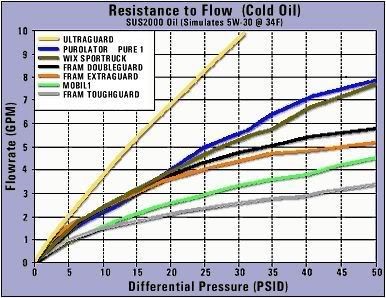
From what you describe they do seem to have the right test rig and even heated the oil to operating temperature. This is far beyond the capabilities of most if not all members of this forum unless they work in the automotive engineering industry. This is what confounds me the most. The data is not what would normally be expected based on basic engineering principals and assumptions. If it is accurate then there is something more complex going on in the filter that has never been explained on any forum or industry paper I have seen. A possible explanation may be the filter media resistance coefficient is not fixed like that of the inlet or exit holes to the filter but is a value that changes with fluid velocity due to some kind distortion of the media. That is the pores in the filter media may some how expand as the fluid velocity increases. This is just speculation on my part. Another effect not discussed yet is transition from laminar flow to turbulent flow. I assumed the flow is always turbulent. I do not see the characteristics of a laminar to turbulent flow transition in the data provided.


Your theory in red (especially the bold red) above is what I would think also. This could also explain why filtering efficiency seems to suffer as the pressure and flow rate increases in a filter.

As I said earlier ... it seems the classic flow equation doesn't firmly describe filter flow.

As you know ... theory and reality don't always coincide (per the classic equations). Theory and equations need to be tweaked to meet reality if you believe the experimental data. I think this is the case with filter flow characteristics.
 
Originally Posted By: Gary Allan
. ..but seeing as you've sent Soupy into scratching his head on how Baloney is turning in his grave (Bernoulli) ..and going back to read up so he can assure that what you're saying is what he meant all along ...

It's a good thing
lol.gif


I see the new guy (hofcat) is a classic “Bernoulli flow equation” kind of guy - I understand it all, as you should know. Something I tried out here when I too first joined. Gary calls him “Boloney” instead of Bernoulli because he can't come to grips over the classic tech side of fluid flow.
wink.gif
 
Originally Posted By: hofcat

That famous graph showing the pressure drop across different brands of filters with the at different flow rates is also suspicious to me. The Fram ToughGurard pressure drop curve has the expected characteristics. Many of the others do not. The curves should look like a parabola turned on it side, not a straight line.


Forgot to point out that the curves on the "famous graph" do have the same basic shape as the data provided by Purolator for the PL14006 in this thread. Look closely at the graph axis labels. The PSID is increasing with increased flow rate, and have similar slopes (delta PSID/delta GPM is increasing).

Also keep in mind that the graph below is data with cold, viscous oil instead of hot thin oil. This factor could change the slope of the flow vs. PSID curve. If you ran the flow test on one filter at different oil temperatures, you would probably see a family of curves with different slopes.

pi_filt_oil_gold_coldoil_thumb.jpg
 
The resistance to flow is not simply related to the square of the flow. It depends whether the flow is laminar or turbulent. More specifically, it is related to the Renolds number. It would be nearly impossible to calculate the renolds number for a filter, because it is tough to determine the size of the openings in the filter. I think in the end the flow through a filter element is to complicated to calculate, and/or predict.
 
Well, while I can't speak in Renolds or whatnot. We can probably assume that the flow is primarily laminar (except with something like a "spinflow") in that the oil will shear and slow as it descends into the depth of the can. No need to travel further than it has to to exit the filter. Now the pores will have varied turbulent impact based on velocity. (and before someone mentions it) ..this would surely be altered by loading as you view this over the entire filter life span ..but that's not essential for discussion's sake.

You have to view something like that outside of the micro processes that are going on inside it. Which, btw, is the only way I was able to evaluate it ..actual physical events observed.
 
If the flow is laminar or turbulent depends on many factors. The strongest factor is the velocity of the flow. I would suspect that at the higher flow rates through the filter that the velocity is getting up there and the flow is most likely all turbulent. It really doesn't take much to make fluid flow turbulent. Reynolds and Bernoulli were buds in the science world of flow dynamics.
wink.gif
 
Shamus= when fluid flows it doesn't all move at once. In a pipe, it's like a telescopic antenna. The outer layer is slowed by the friction with the exterior of the conduit. In calculating water flow rates for drainage systems you actually factor whether its a cement aqueduct or a convoluted metal ..etc..etc.

Anyway, the layers "shear". The more the friction of the exterior layer, the more mircro turbulence/friction it transmits to the next layer and it cascades inward toward the center.


Top image is turbulent ..the lower is laminar.

laminar.gif


image2.gif


this is a depiction of a "metered orifice" flow meter. Basically it can integrate the flow rate by the pressure differential across a fixed orifice plate.

Note how the smooth laminar flow is "companded" (compressed then expanded) and the compression and void zones that are created on either side of the walls of the orifice plate. At relatively low flow rates ..not a big deal. Higher flows ..bigger deal.

Orifice-ed.jpg
 
If you hang out here long enough, you manage to pick up a few things via osmosis. A few of the upper brain pan persuasion will give a try at speaking mortal.
grin2.gif
 
issues_sol_1_eddy.jpg


Here's a depiction of the eddies created by an orifice. Lacking the knowledge and discipline to describe them intelligently, I'll simply state that they tax flow. In a positive displacement environment, they create a pressure elevation that quantifies the additional "power" (perhaps force would be a better term) required. The fluid is accelerating and decelerating through the choke.

What is the most disputed aspect of this, as it's used to depict the appearance of a filter, is that while it is a bona fide state (as depicted), it would not appear that way ..nor react to nearly that magnitude of severity, if a like choke of extremely smaller proportions were located down stream of it (that being the engine). Flow would much more easily compress and expand ..eddies would be far less turbulent and far less "taxing".

That's why, for most cases that one could site, under most conditions one can create, the filter is invisible while under positive displacement conditions. Naturally, there can and will be exceptions and once out of positive displacement flow conditions, YMMV.
 
My main point was that the resistance vs flow is not a linear relationship, nor is it a squared relationship. The formulas used to describe the resistance change as the flow goes from laminar to turbulent.

As a side note, turbulent flow decreases resistance sometimes. That is why golf balls have dimples.
 
Originally Posted By: Gary Allan
What is the most disputed aspect of this, as it's used to depict the appearance of a filter, is that while it is a bona fide state (as depicted), it would not appear that way ..nor react to nearly that magnitude of severity, if a like choke of extremely smaller proportions were located down stream of it (that being the engine). Flow would much more easily compress and expand ..eddies would be far less turbulent and far less "taxing".


Depending on the flow rate through the filter and the design of the filter, some of the flow could have pretty high velocities and easily become very turbulent. In the case of the PL14006 PureONE filter test date (given by Purolator Sr. Engineer) at the beginning of this thread, the filter was tested to 18 GPM of flow. Just imagine 18 GPM (or even 8 or 10 GPM) going through the holes in the filter's base and the holes in the center core tube. Obviously, at higher flow volumes, these orifice streams will become pretty high velocity.

Originally Posted By: Gary Allan
That's why, for most cases that one could site, under most conditions one can create, the filter is invisible while under positive displacement conditions. Naturally, there can and will be exceptions and once out of positive displacement flow conditions, YMMV.


Yes, agreed that if the pump is not in relief mode the filter is basically "invisible" only in the respect to the effect it has on the engine oil pressure (ie, the pressure after the filter). Only after the pump hit's pressure relief point is when it's possible to tell the difference in flow resistance of different filters used on an engine. But, that doesn't mean the PSID in the filter is zero ... the pressure drop is still there ... you just don't know it unless you put a delt P instrument across it. What it means is the oil pump output pressure will just increase to overcome the added resistance, up to the pressure relief point. Once there, the “effective resistance” of the filter will be apparent.
 
Quote:
Just imagine 18 GPM (or even 8 or 10 GPM) going through the holes in the filter's base and the holes in the center core tube. Obviously, at higher flow volumes, these orifice streams will become pretty high velocity.


Just imagine the velocity through a .75^2 pipe transitioning from a 2x4 cylinder centerwell @ 18gpm ..or just 8-10 ...THEN getting processed through an even tighter choke
 
Originally Posted By: Gary Allan
Quote:
Just imagine 18 GPM (or even 8 or 10 GPM) going through the holes in the filter's base and the holes in the center core tube. Obviously, at higher flow volumes, these orifice streams will become pretty high velocity.


Just imagine the velocity through a .75^2 pipe transitioning from a 2x4 cylinder centerwell @ 18gpm ..or just 8-10 ...THEN getting processed through an even tighter choke


True ... at high GPM flow rate, the oil is obviously screaming pretty fast through some of the tight passages in the system. Keep in mind though, that the main engine gallery is usually relatively large, and splits off to many smaller branches, so the total flow volume is split into multiple paths inside the engine.

The PL14006 PureONE was tested to 18 GPM of hot oil ... even though it was hot/thin oil, the fact is 18 GPM is a ton of volume. Most garden hoses don't even put out half that flow volume. It would be interesting to be able to actually see the oil flowing at that pace through a filter with a clear/see through can.
 
Originally Posted By: hofcat
They do talk this way in engineering circles. It can be a challenge to describe fluid dynamics equations and principals to those who have not worked in this field, but I try.


You do a good job.
 
Originally Posted By: SuperBusa

The Engineer at Purolator actually tested the PL14006 on their flow bench and sent the "Flow vs. PSID" test data, along with some other inputs. This is their response:
--------------------------------
"The test stand was set at 203 degrees F. Note the higher temp will lower the viscosity of the oil even more. So at 212 degrees F the differential pressure of the filter will be even slightly lower. The test oil used is very close to the same viscosity of 11.3cST at the tested temp."
--------------------------------

He sent an Excel file with the test data (shown below), and a plot. Here is the data, so if you want to see the graph just plot it up in Excel.

Flow (GPM) --- Delta P
1 --- 0.4
2 --- 0.7
3 --- 1.1
4 --- 1.5
5 --- 1.9
6 --- 2.3
7 --- 2.7
8 --- 3.2
9 --- 3.6
10 --- 4.1
11 --- 4.7
12 --- 5.2
13 --- 5.8
14 --- 6.4
15 --- 7.0
16 --- 7.6
17 --- 8.3
18 --- 8.9


river_rat plotted the above data and the graph is shown below ... thanks river_rat!

PureOneflowdata.jpg
 
Originally Posted By: Jim Allen
And what is the bypass setting on that filter?

PL14006 has no bypass valve.

Most PL's run 12-15 psi, if they have one.
 
Status
Not open for further replies.
Back
Top