Using an existing 4 conductor wire to supply a 220 v surface mounted heater with electric fan

Joined
Dec 31, 2017
Messages
15,341
Location
SE British Columbia, Canada
We have a Lions Club storage building that basically froze inside during the last cold snap. There is a metal clad cable with four conductors inside it. The heating unit does not have remote thermostat and there is no adjustable thermostat on the unit. We’re not convinced it was getting the full 220 V, and the also the unit was shutting off at too low of a temp.

The line to the heating unit has a red and black, both hot, a white neutral and a green ground. The heater just has a red and black, but no white. The unit does have an electric fan and the fan blows hard.

I take it the white neutral is used to help power the 110 V motor and the red and black hot wires power the heating element. What happens with the white wire? We can’t see where this wire goes and we’re concerned the unit was wired wrong. I suspect the fan was wired with one white and one black, and the red and Is powering the coil, but the black is not. We’ll be taking a look later this week. Currently, everything is wrapped with electrical tape. The clad cable is connected to two 15 amp breakers latched together. Any ideas? Thanks. Yes we know to get an electrician but we want to see if we need a new heating unit first. Thanks.

You tube doesn’t seem to address this case very well.
 
Last edited:
You’re almost going to have to put a meter on it when it’s running to see what voltage you’re getting to the element. Normally white is neutral, connected to ground in the breaker panel-the fan would have to be connected to one of the hot leads to have any power. Possibly the element is only getting 110V?
 
You’re almost going to have to put a meter on it when it’s running to see what voltage you’re getting to the element. Normally white is neutral, connected to ground in the breaker panel-the fan would have to be connected to one of the hot leads to have any power. Possibly the element is only getting 110V?
Yes, if the fan was not there it would be a simple matter of connecting the red to one of the leads to the coils and the black to the other lead to the coil. Somehow the white is connected to one side of the motor and say, the black, is connected to the other side of the motor. Yes, like you said, its possible the element is only getting 110 V. We looked at an identical unit we bought on spec and then realized it may be a wiring issue. I'll take some pics of the identical one.
 
Years ago, I wired a new dryer element and a young tech at work said you just connect the red to one end and the black to the other end. I guess because they are not in phase, the black wire is the ground for the red and the red wire is the ground for the black. Does that sound right?
 
If it's a 240 volt heater, the fan should be 240 volts and connected directly in parallel with the element. A neutral wire is seldom if ever used with wall mounted electric heaters.

Measure the voltage between the red and black wires and confirm it is 240.
 
While I wait for my photos to load off the cloud, let me describe what I say. The red and black are bolted to the opposite sides of the coiled heating element. I see the motor is pulling voltage off these two wires. One side of the motor appears to be pulling power off the red. The other side of the motor is pulling power off the black wire. I guess that suggests that yes, it is a 240 V motor. Its such a small little thing its hard to believe it 240 V. There might be a transformer off to the side of the motor. Anyway, there is no place for the white wire so I assume I can snip and cap it. Right now, whoever wired this thing, has incorporated the white wire into wiring. Yikes!
 
Years ago, I wired a new dryer element and a young tech at work said you just connect the red to one end and the black to the other end. I guess because they are not in phase, the black wire is the ground for the red and the red wire is the ground for the black. Does that sound right?
Well, not really “grounds”, just opposite sides of the same 240V sine wave. Ground (or neutral) would technically be in the middle. That’s why red, or black, to ground is 120V.
 
While I wait for my photos to load off the cloud, let me describe what I say. The red and black are bolted to the opposite sides of the coiled heating element. I see the motor is pulling voltage off these two wires. One side of the motor appears to be pulling power off the red. The other side of the motor is pulling power off the black wire. I guess that suggests that yes, it is a 240 V motor. Its such a small little thing its hard to believe it 240 V. There might be a transformer off to the side of the motor. Anyway, there is no place for the white wire so I assume I can snip and cap it. Right now, whoever wired this thing, has incorporated the white wire into wiring. Yikes!
I bet white/neutral is going to one side of the element, which would only give you 1/2 power. Put red to one end & black to the other, I bet you get full heat then!
 
Here are some shots. This is the unit I purchased to replace the existing one . Turns out they are the same. In one pic you can see two fine black wires that lead to the fan motor. Turns out one is connected to the black wire and one is connected to the red wire. I take it the red item is a high temperature cutoff or else the thermostat that the unit is set to. Looks like it says 40 F. I would prefer 68 F. Any ideas? Thanks.


65351E21-4176-4B6E-9E91-0001F9DA969B.jpeg
AD7F4AC4-B682-4CF1-B81D-62F97382DE80.jpeg
9E327429-796B-4DF8-95C1-08B4BF498129.jpeg
78A4F3C7-C8C5-4B5F-8706-85EB32F6AB95.jpeg
7B529D6F-230E-4002-99D7-7CD49FF1F7A8.jpeg
A4EF0B2A-83D7-4D62-A1F7-77B295DCF614.jpeg
 
Last edited:
Are you sure the fan motor is 120V? If there is no white wire connection on the unit, then don't connect it anywhere.

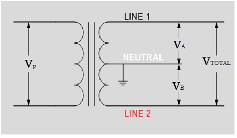
The white neutral is the middle tap on a transformer. (The USA configures power this way for "safety" reasons, as the neutral is also connected to the ground in the breaker box)

Between line 1 and 2 there is 240V
Between line 1 and neutral, there is 120V
Between line 2 and neutral, there is 120V

Centre-Tapped-Transformer.jpg
 
I have no clue if what was code in 1985 is OK today, but 12/2 was used to wire my electric heat. Black, white and bare. Each jacketed conductor went to a breaker and the bare went to the ground buss which was bonded to the neutral buss. Cujet is using 12/3 Romex, not 12/2. Each is electrically sound. 12/3 is sounder. You need a volt meter. :cool:
 
Last edited:
I will check the voltages. Regarding the red gizmo, I see it’s a thermal cutout with a low setting at 40 F. Not sure if the high number is 175 F. I would imagine the inside of the case is pretty hot from those coils. We found the unit is cutting out at just around freezing and is not keeping the room warm.
 
I will check the voltages. Regarding the red gizmo, I see it’s a thermal cutout with a low setting at 40 F. Not sure if the high number is 175 F. I would imagine the inside of the case is pretty hot from those coils. We found the unit is cutting out at just around freezing and is not keeping the room warm.
check the breaker panel should be a 2 pole brkr maybe one line is off??
 
  • Like
Reactions: JC1
I will check the voltages. Regarding the red gizmo, I see it’s a thermal cutout with a low setting at 40 F. Not sure if the high number is 175 F. I would imagine the inside of the case is pretty hot from those coils. We found the unit is cutting out at just around freezing and is not keeping the room warm.
175 is the cut out temperature. 135 it will cut back in. The 40 is how many degrees below the cut out that it cuts back in.
 
The thermal cutout is not to regulate the room temperature. It protects against internal overheating such as from fan failure or blocked airflow. It stays closed at all times in normal operation. The heater will run all the time that power is supplied to it. If you had a voltmeter (a common theme in any thread about an electrical system) you could test if power is being supplied when it is not running.

If the unit does not have a dial thermostat on the front for the user, it would be installed with an external thermostat in series with the power supply. It looks like you just haven't found the external thermostat yet.
 
  • Like
Reactions: JC1
Here are some shots. This is the unit I purchased to replace the existing one . Turns out they are the same. In one pic you can see two fine black wires that lead to the fan motor. Turns out one is connected to the black wire and one is connected to the red wire. I take it the red item is a high temperature cutoff or else the thermostat that the unit is set to. Looks like it says 40 F. I would prefer 68 F. Any ideas? Thanks.


View attachment 199903View attachment 199904View attachment 199905View attachment 199906View attachment 199907View attachment 199908
I have been corrected on the function of the Temp cutout. The proper way to read the printing is that it functions at 175 F - 40 which is 135. This gives it an operating range , measured inside the metal body, of 135 to 175 F. Any higher, and the power to the coil assembly is cut off. The ambient temperature on the room is whatever the heat loss causes it to be. Also, the unit is always on and the manual on-off is controlled at the electrical panel. I’ll check for voltages.
 
I have been corrected on the function of the Temp cutout. The proper way to read the printing is that it functions at 175 F - 40 which is 135. This gives it an operating range , measured inside the metal body, of 135 to 175 F. Any higher, and the power to the coil assembly is cut off. The ambient temperature on the room is whatever the heat loss causes it to be. Also, the unit is always on and the manual on-off is controlled at the electrical panel. I’ll check for voltages.
Where is the thermostat? seems like its setup for an external thermostat?
 
Back
Top