Originally Posted By: mk378
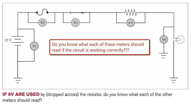
An ideal closed switch or un-blown fuse has zero resistance, thus zero volts for V2 and V3 in the first circuit.
Circuit is working correctly so we can assume these:
V1 Battery: charged = 12 volts. Of course a real battery is not exactly 12 volts.
V2 Fuse: not blown = zero volts.
V3 Switch: closed = zero volts
V4 Bulb: not burnt out = gets battery voltage minus the drop across the resistor, so 6 volts.
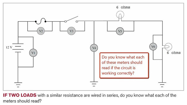
In circuit 2, the switch is open, so the entire battery voltage will appear across the switch (V3). Everything downstream of the switch is turned off, zero volts.
Yes that looks like a good answer to me and well explained. Nice work.
I'll just add that the assumption is an ideal volt meter that offers infinite resistance, so it doesn't steal any voltage when taking a measurement.