Good old Made in the U.S.A. audio gear. I bought this piece used many years ago at a substantial discount from its new ($3450) retail price. It was manufactured at the now closed Madrigal plant in Connecticut where they also produced Proceed.
I used it daily for nearly 15 years before one day it failed to light. The problem turned out to be an overheated & burned-out main power supply transformer. With Madrigal long out of business, I thought the Citation 7 was too. A search turned up no replacement, so I thought of assembling a new power supply in another box. Then while searching for transformer manufactures in the USA, I discovered the company that made the transformer for Madrigal was still in business. After talking back & forth and many emails, I placed my order. After a long wait of 4 months, I had a new one in hand.
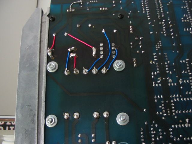
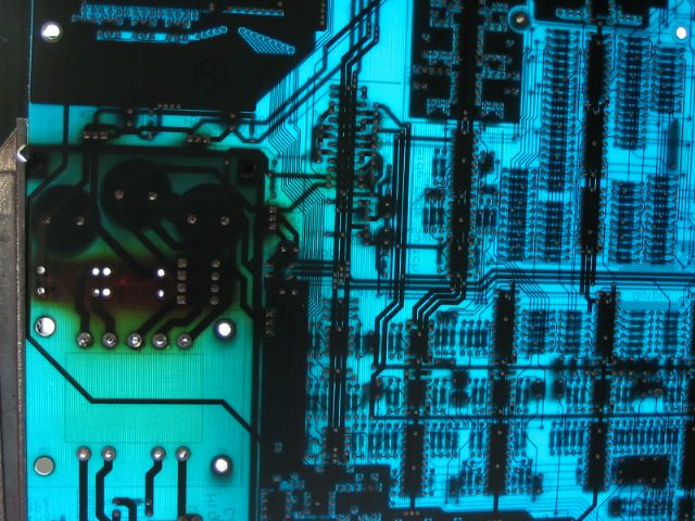
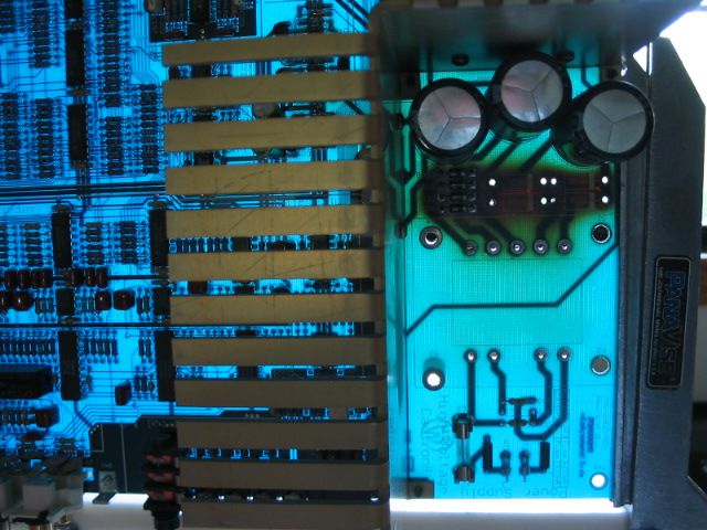
Now, back to the board photos..further investigation revealed long-term heat damage to the main PC board. This is best revealed here in backlight, which is very effective for finding board hot-spots. Notice the yellowing of the blue fiberglass board on the left hand side. The three main electrolytic capacitor terminals can be seen. The extreme brown area below them is where the main power diodes were mounted...right close to the board (big mistake). They need to be up a bit to provide better cooling and prevent this kind of heat-related damage.
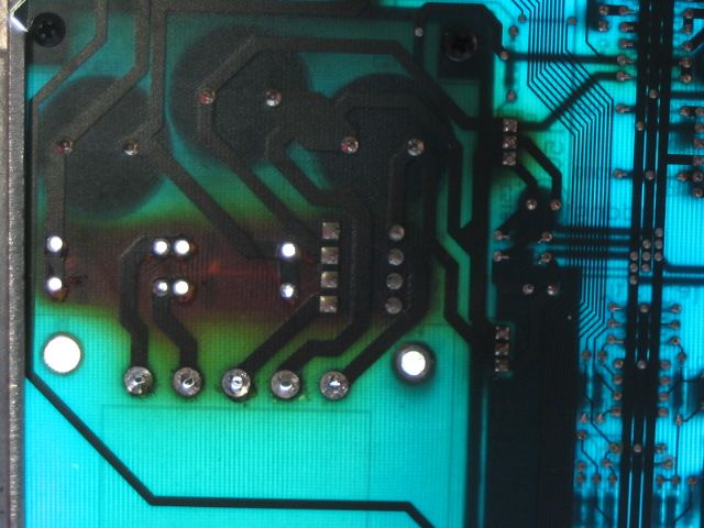
Zooming in here, you can also see signs of over-heating on one of the regulators mounted to the heat sink. It's the three vertical pins to the right of the PS main caps.
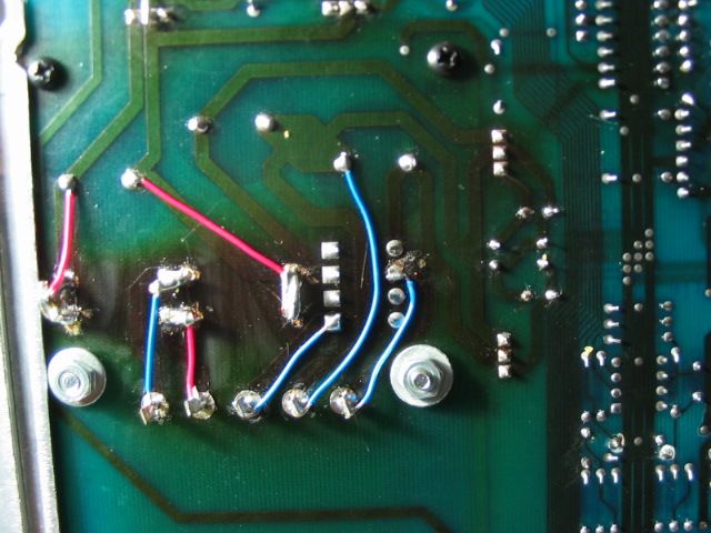
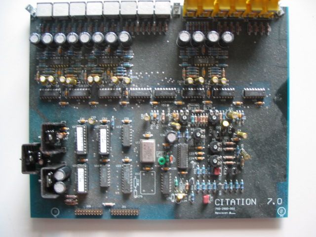
Here's the view from the other (component) side. I've removed the power diodes, thus the empty holes. They'll be replaced, along with the smaller units to the left and the the main PS caps in the background. Surely they must be 'cooked' after years of exposure. The PS transformer mounts below.
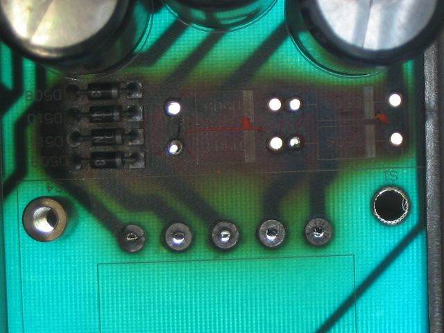
Note the very large heat-sink for the main regulators.Too bad the diodes weren't heat-sinked.
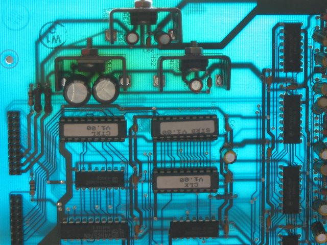
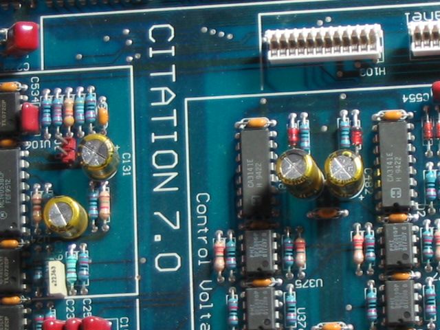
Here's a section of the video switching board showing heat damage from a regulator. It's easy to tell which one of the three is drawing the most Watts. I'll be replacing each of the regulators, their associated caps and resistors.
Here's the same (dusty) board front-lit.
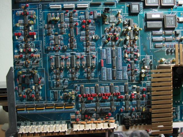
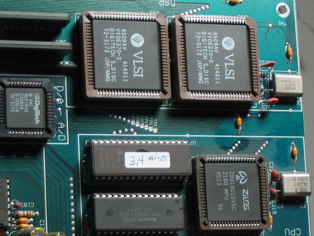
Here's the main board front-lit. The layout makes troubleshooting much easier. Madrigal did a nice job of labeling various sections of the board and the schematics were still available from Harmon Int'l.
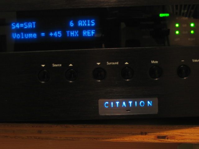
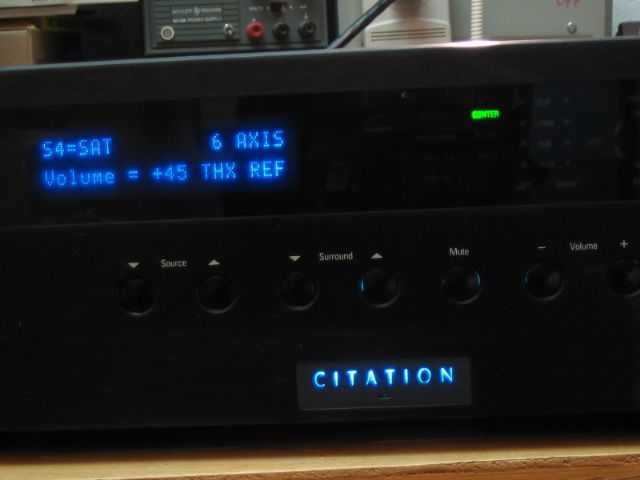
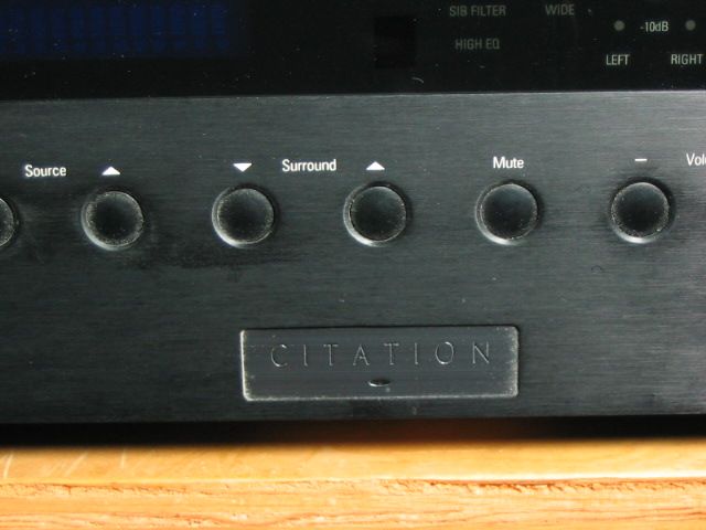
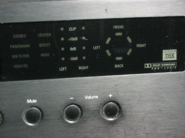
Here's some front-panel photos.
I'm looking forward to getting her lit again and enjoying surround sound, now that the replacement transformer has been received.
Stay tuned for updates!
I used it daily for nearly 15 years before one day it failed to light. The problem turned out to be an overheated & burned-out main power supply transformer. With Madrigal long out of business, I thought the Citation 7 was too. A search turned up no replacement, so I thought of assembling a new power supply in another box. Then while searching for transformer manufactures in the USA, I discovered the company that made the transformer for Madrigal was still in business. After talking back & forth and many emails, I placed my order. After a long wait of 4 months, I had a new one in hand.
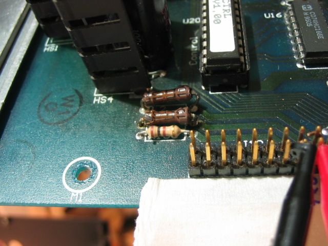
Now, back to the board photos..further investigation revealed long-term heat damage to the main PC board. This is best revealed here in backlight, which is very effective for finding board hot-spots. Notice the yellowing of the blue fiberglass board on the left hand side. The three main electrolytic capacitor terminals can be seen. The extreme brown area below them is where the main power diodes were mounted...right close to the board (big mistake). They need to be up a bit to provide better cooling and prevent this kind of heat-related damage.
Zooming in here, you can also see signs of over-heating on one of the regulators mounted to the heat sink. It's the three vertical pins to the right of the PS main caps.
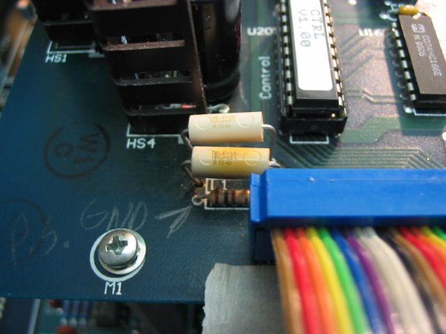
Here's the view from the other (component) side. I've removed the power diodes, thus the empty holes. They'll be replaced, along with the smaller units to the left and the the main PS caps in the background. Surely they must be 'cooked' after years of exposure. The PS transformer mounts below.
Note the very large heat-sink for the main regulators.Too bad the diodes weren't heat-sinked.
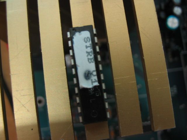
Here's a section of the video switching board showing heat damage from a regulator. It's easy to tell which one of the three is drawing the most Watts. I'll be replacing each of the regulators, their associated caps and resistors.
Here's the same (dusty) board front-lit.
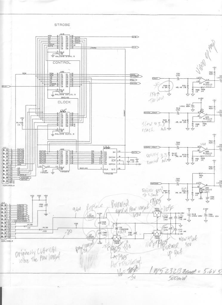
Here's the main board front-lit. The layout makes troubleshooting much easier. Madrigal did a nice job of labeling various sections of the board and the schematics were still available from Harmon Int'l.
Here's some front-panel photos.
I'm looking forward to getting her lit again and enjoying surround sound, now that the replacement transformer has been received.
Stay tuned for updates!