Ceiling Fan Wiring

Status
Not open for further replies.
Joined
Jan 30, 2007
Messages
17,501
Location
Clovis, CA
Years and years ago I broke the little chain that goes into the fan speed switch. Assuming that the new switch would come with the wires attached like an automotive switch, I threw the switch away along with its attached wires. Big mistake; with no wiring diagram and no attached wires to the new switch, there was no way to determine how to wire the switch up.

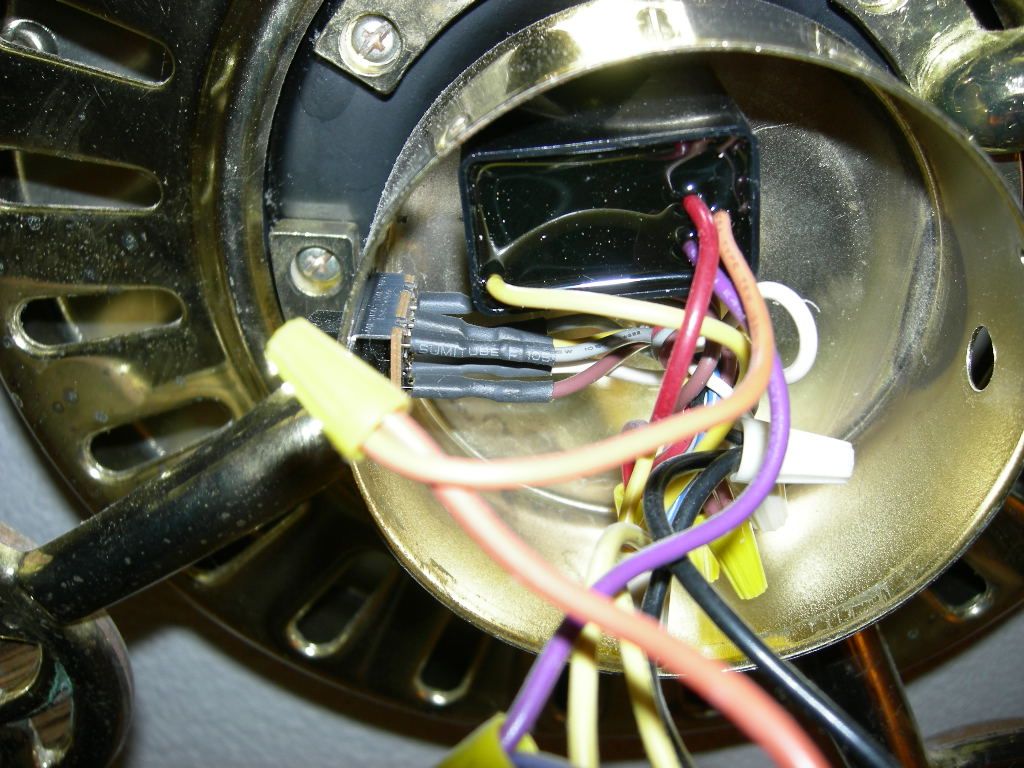
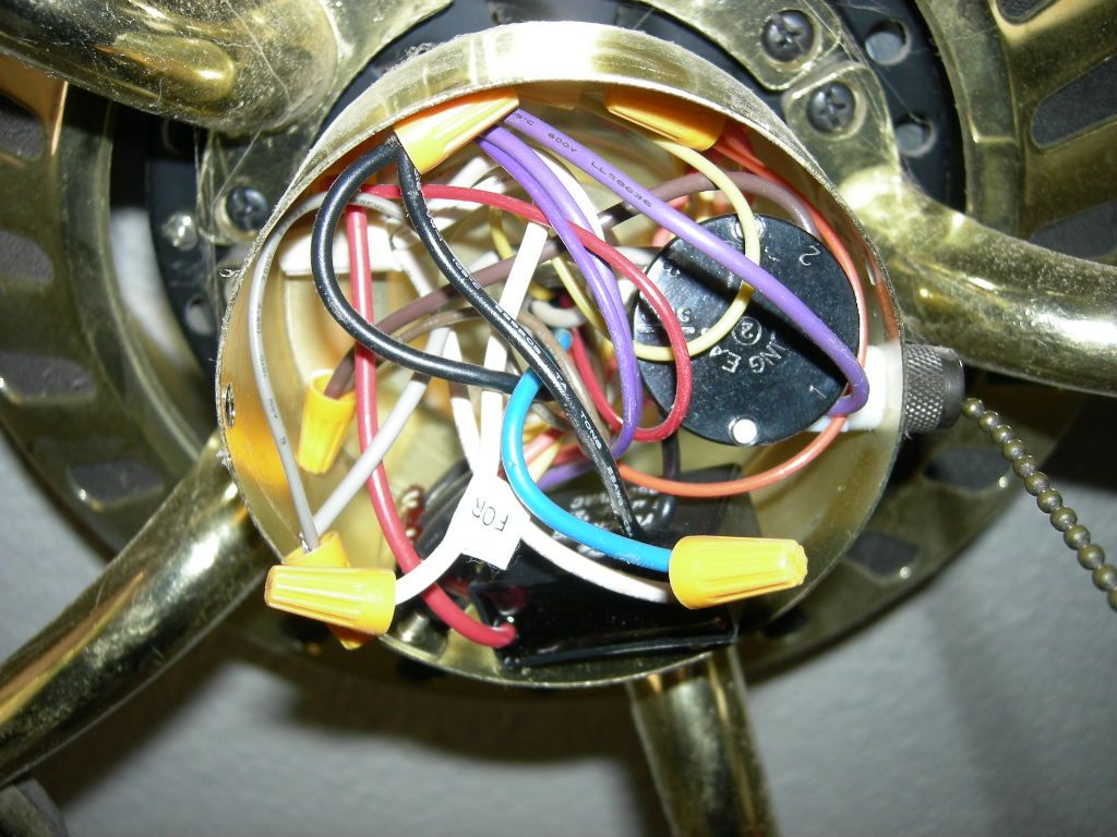
So this week I had a brilliant idea: I'd pull the cover off of a known good ceiling fan in the other room and see if I could copy the wiring from it. No dice; the wiring is different and the wire colors are different. But one thing they both have in common: they both have a 6-wire reverse switch and they both take a 4-wire speed switch. The only thing different is one fan uses a 4-wire capacitor and the other known good fan uses a 2-wire capacitor.

Both fans are stand alone fans with no wall switches and no lights in the circuit. You would think that finding a wiring diagram on the internet would be easy, but no. And if you buy a new fan, do you think they'd include a wiring diagram for the inside of the fan? No, they just give you a wiring diagram telling you how to hook the fan up to your house; no internal wiring diagram included in the user manual. This stuff is ridiculous as heck. There should be some kind of standardization of wiring between all makes of fans and the internal wiring diagrams should be easy to find.

DSCN1904_zpscjfdwiuy.jpg


DSCN1879_zpsi4z6ulmw.jpg
 
They could easily put a label in the fan itself.

We need more regulations!

27.gif
 
That's how most major appliances are, but ceiling fans are not considered major appliances I guess.
 
The fan lobby probably persuaded a senator that an exception was vital for jobs in their state.
 
If you need a wiring diagram to change the switch on your fan, i suggest hiring a handy man.
 
Originally Posted By: bvance554
If you need a wiring diagram to change the switch on your fan, i suggest hiring a handy man.


I could pull the speed switch out of your ceiling fan with the attached wires and you'd be in the same boat.
 
Originally Posted By: Merkava_4
Originally Posted By: bvance554
If you need a wiring diagram to change the switch on your fan, i suggest hiring a handy man.


I could pull the speed switch out of your ceiling fan with the attached wires and you'd be in the same boat.


I don't know if that made you feel better, but I wasn't knocking you. If you had a multi-meter and knew what you were doing you could wire it up. Again... not attacking you, just suggesting having someone else do it. Or buy and install a new fan.
 
Originally Posted By: bvance554
I don't know if that made you feel better, but I wasn't knocking you. If you had a multi-meter and knew what you were doing you could wire it up. Again... not attacking you, just suggesting having someone else do it. Or buy and install a new fan.


What I need to know is how the circuit works and the direction of current flow in the circuit -- that would make me feel better.
 
Originally Posted By: Merkava_4


What I need to know is how the circuit works and the direction of current flow in the circuit -- that would make me feel better.


I can help there. The current flows in one direction for 8.3ms and then the other direction for 8.3ms and this continues for as long as you have a complete circuit.

What you *really* seem to want to know is the phase relationship between the start and run windings and which phase makes it go in which direction, how the run capacitor is configured and how the whole mess is switched. I'd start with a multi-meter and a piece of paper. Draw out your components after identifying which is which with the meter and assemble them in something vaguely resembling a working circuit. Tweak until you have it running to your satisfaction.

(edit) Actually its easier than that as your windings are still wired to the reversing switch. You just need to figure out which wires on the run-cap are for which speeds and wire those to the new switch.
 
Last edited:
I'm no electrician which is why I'm wondering how an electrician would handle it. Say if somebody robbed the switch out of one of his ceiling fans; would he figure it out, or would he throw the fan away? I suppose he would have an identical fan laying around and he would use that one to see how the wires are rigged.
 
If he was worth his salt he'd just figure it out. It's actually not that hard. if you understand basic circuit theory, but it's not something one can really teach over the net by remote control. If I give you advise and it turns out your Chinese capacitor is hooked up differently to most then there is a real potential you might get hurt or worse. I do realise that you guys only play with toy electricity (110V), but there is still a danger.

The fact you actually have to ask a forum for advise indicates you should probably do some research and learn about this stuff, or let someone who actually knows what they are doing spend 5 minutes and do it for you before you either die trying or burn your house down.

I know what I can and can't do without dying or burning my eyebrows off, but that 40 years of knowledge can't be imparted on a web forum half way around the globe, and stuff that is common sense to me (don't do that or it might kill you) is probably not common sense to you.

The reality is that switch is likely in the active line and simply switches the incoming voltage across one of three wires in that capacitor. Low, middle & high speed. 4 wires on the switch, 3 wires on the capacitor and one wire coming in.
 
Since the fan motor runs on AC, capacitors are used to control the speeds instead of resistors, which would dissipate heat and might melt something.

The hot wire will always go to the switch first, for safety reasons. HIGH speed will probably be no cap at all. MEDIUM speed will be one value of cap. and LOW will be another. All the switch does is connect HOT to each of these in turn, with each pull.

I'm willing to bet the instruction manual is on-line. Inside should be a wiring diagram. Failing that, call the manufacturers hot-line.

I always snap pictures of things before I take them apart, especially where wiring is involved. A picture is worth a thousand words it's said....
 
Originally Posted By: Brad_C
If he was worth his salt he'd just figure it out. It's actually not that hard if you understand basic circuit theory, but it's not something one can really teach over the net by remote control.


But I do understand basic electrical theory; that's why I'm being so stubborn about this. And there's only two things that you can't teach over the internet: welding and surgery.
 
Sleddriver -- Do you happen to know why one fan would have two wires coming out of the capacitor and the other fan would have four?
 
A very simple observation; given that you most likely have a pull chain type of reversing switch, how would you know that you have wired it "wrong"? Won't it just toggle?
 
Originally Posted By: Merkava_4
Sleddriver -- Do you happen to know why one fan would have two wires coming out of the capacitor and the other fan would have four?


The fan that has 2 wires likely uses inductive speed control, where multiple or tapped windings are used to control the power whereas the fan with 4 wires would use capacitive speed control. The former should have 6 wires coming out from the windings whereas the latter should have 4.

A capacitor is *required* in conjunction with the induction of the start winding to provide the phase shift that starts the motor, so don't try and bypass the cap for high speed mode as previously suggested as you'll just end up with a vibrating noisemaker that hums and needs a manual shove to get it spinning.
 
Originally Posted By: Merkava_4
Sleddriver -- Do you happen to know why one fan would have two wires coming out of the capacitor and the other fan would have four?

Different number of speeds?
21.gif


My ceiling fans are all old style, two-speed Hunters. No capacitors. I have hung a few of the newer ones though, with multiple caps. You should be able to get it running without a switch first, just connecting the wires using wire nuts. Find hot and neutral using a voltmeter or AC sensor. In wall wiring, black is hot, white neutral, green ground.

That may not be so in the fan however. You can drop the flange cup at the ceiling, that hides the hanging hardware & box, and have a look in there.

Out of your multiple-tap-black-cap, ylw looks common to red, orng & prple. So hook AC neutral to a fan wire, the other fan wire to ylw, your choice of rd, orng or pur to hot and turn on the power. It should spin.
 
Status
Not open for further replies.
Back
Top