Phoenix Project II: Servo100 Amp Resurrection

Status
Not open for further replies.
Joined
Feb 6, 2010
Messages
4,836
Location
Central Texas
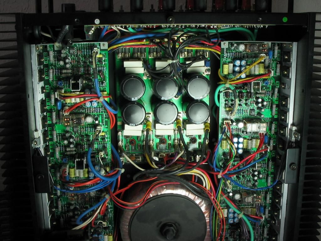
This one had been collecting dust for far too many years. I recently decided to resurrect it along with the loudspeaker shown in the Photo forum.

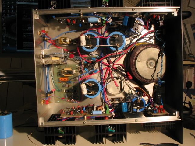
I built this from scratch about 22 years ago, including the aluminum chassis. My first audio metalworking project. Quite a learning experience. Drilled and tapped LOTS of holes...mostly in the correct place.

This amp quit working several years ago and I quickly substituted a DH220 in its place. Then recently, the DH220 quit! So I've been without the four 12" drivers that make up the bass section of my reproduction system!

I slowly powered it up using a VARIAC, one channel at a time, fed it a 1kHz sine wave and observed the output on the oscilloscope. IT looked fine. So I ran some power tests and noted that the voltage rail regulators were sagging about 5V when the amp was delivering 90W to an 8 Ohm load. They shouldn't sag at all.

So I bypassed them and redid the power testing. This time I measured 140W RMS into 8 Ohm at clipping, per channel but not both channels driven simultaneously as I only have one load.

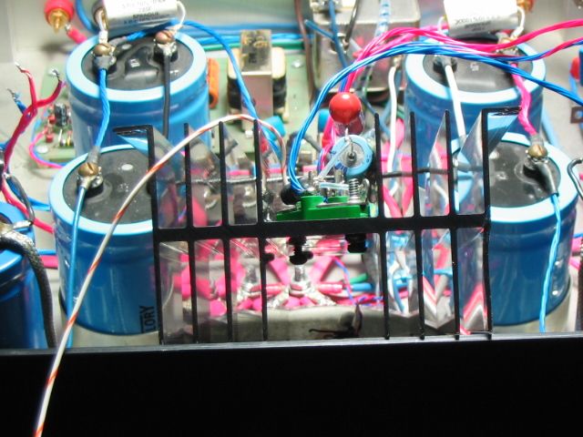
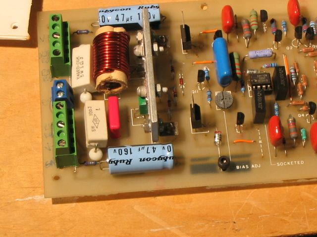
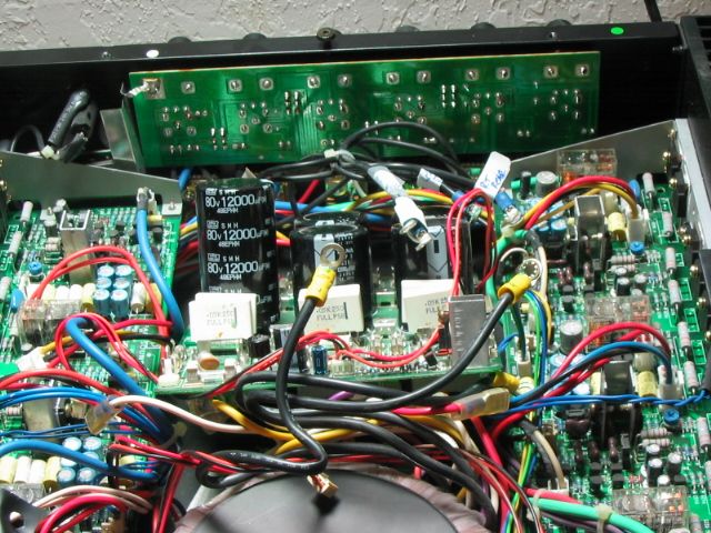
I removed and began troubleshooting the regulators and discovered the main fault lay in the wrong zener choices and not enough voltage overhead to keep them in regulation under load. Another issue to account for is my outlet Voltage tends around 125VAC instead of 117VAC. As such, the 500VA torroid used buzzes. You may recall a similar issue with the HK Citation 7 I resurrected earlier in this forum. It was clearly not designed to run at an elevated outlet voltage and as such, had cooked itself to death: Overheating regulators, heatsinks too hot to touch, toasting the main ckt board, peeling board traces, etc. It's now only turned on with the master switch when needed.

Back to the amp at hand....the regulators are now working properly and no-load to full-load Voltage drop is now within 0.1VDC! Quite an improvement in regulation!

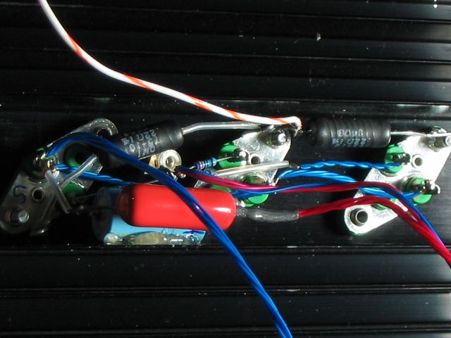
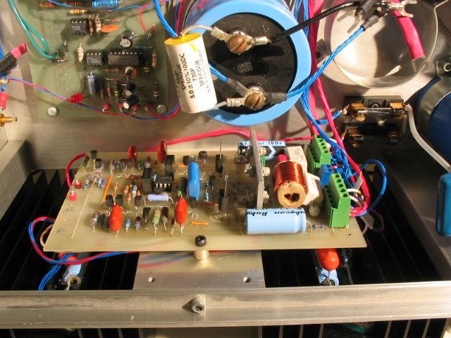
I currently have the MOSFET heatsinks out to install some 0.22 Ohm source resistors. These ensure equal current sharing and provide some source degeneration and local feedback to stabilize the output devices.

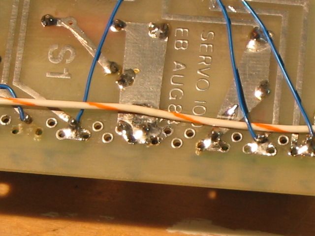
I've also removed the driver boards to update the I/O connections from wires directly soldered to the boards to using terminal blocks instead. This greatly enhances board removal and prevents PCB foil damage from repeated in & out.

I'll post photos later. It'll be great having this custom amp back in service. Then I can put the DH220 on the bench. I also have a Parasound 5 ch amp that has begun to hum through the loudspeakers. I suspect the electrolytic caps have aged, the capacitance has fallen and thus noise is getting though the power supply. It may be time for a 're-cap'...litterally.

Stay Tuned!
 
Back-side of output heatsink, showing three transistor sockets. Black cylinders are the new source resistors mentioned above. This channel is barely wider than the sockets!
BoakRegs006_zps668a65d6.jpg


Here's a side-view of an output heat sink. Note the narrowness of the channel to fit components! Back ground shows raw PS electrolytic capacitors.
BoakRegs008_zpscba03b36.jpg


Here's one of the two driver boards. The output MOSFET'S are mounted on the heatsinks shown above. Note the green & small blue terminal blocks on the left edge of the board. Previously this was a nest of wires soldered in place. Makes for an excellent permanent installtion, but frustrating and damaging to the PCB foil when troubleshooting.
BoakRegs009_zps4f5ab35d.jpg


Backside of driver board showing jumpers to repair damaged foil traces.
IMG_7601_zps5b0948b1.jpg
 
We had a problem with Philips C-80 television chassis B+ regulator transistors.
It was a regulator transistor (TO-3) that would get quite hot under high line voltages and Philips added series dropping resistors to the transistors heat sink that ended up looking like your assembly.They dissipated some of the heat but would not allow full B+ under heavy load as you describe.

Under high line voltage and with an original regulator (without added resistors) the transistor/heat-sink assy. would cook.

Under low line voltage (still in acceptable 10% range) with a regulator transistor/dropping resistor set-up the regulator transistor would be cool and unstable because the resistors were dropping the voltage under load... dropping voltage below regulator circuit adjustment.


The answer came to home entertainment electronics products in the form of SMPS power supplies which were a blessing (if well designed).
 
That describes the HK Citation pre-amp I worked on earlier: Not designed to deal with 125VAC line level. Too much drop across the three terminal regulators, causing excessive power dissipation, heat sinks & main power transformer too hot to touch and shortened component life.

I'm going to go back in there with some power resistors to drop some of that excessive line Voltage. After all, resistors are much cheaper than other components! Transformers don't like excessive line voltage as it causes them to run hot & produce excessive noise...especially torroids.
 
Update:

I've reinstalled the MOSFET heat-sinks and driver boards back into the amp chassis. Also straightened out a few wiring issues. The terminal blocks sure make this job easier! What a difference they make.

This photo was taken with the amp sitting on one side. Down below on the left and right are the MOSFET's mounted on heatsinks. Most wiring is hooked up on the right side except for the input, which is presently unconnected on the left board edge. One of the main power supply 10,000uF 74V electrolytic caps is shown above it. There's another to the right I've yet to install. Note the mounting ring mounted to the chassis. The pc-board to the left of the blue cap constantly monitors the output for any faults and temporarily disconnects the outputs upon turn on to prevent turn-on thumps. When any fault is detected, the relay instantly opens to protect the loudspeakers. This is much faster than a fuse.
BoakRegs011_zpsc5cc3d1c.jpg


Here's the 'big-picture'. The amp can be split down the middle from left to right, with each channel occupying a side. Note the 'star-ground' in the chassis center with the many red wires leading to a single termination. In the bottom right hand corner is one of the rail voltage regulators and just to its left is its output capacitor. From there rail fuses protect each board and its output devices. The shiny metal box attached to the rear panel is a commercial AC line filter. The main power fuse is installed just above it. The red disk seen just to the right is a transient voltage surge absorber. It prevents any spike over about 400VAC from getting any further. One final detail is to add a NTC thermistor in the transformers primary to control in-rush current. Large electrolytic caps like these look like a dead short when discharged. If you happen to turn the amp on when the AC waveform is near it's peak value, very large currents occur due to the low secondary winding resistance....enough to weld switch contacts and blow fuses among others. At room temp, the resistance of the thermistor is about 10 Ohms. As soon as several amps flows through it at turn-on, it heats up and its resistance drops to about 0.01 Ohms. I may use it with a timed-relay ckt that will short it after about 10secs. With no current through it, it will cool off & it's resistance will return to 10 Ohms.
BoakRegs014_zpsb7bbd551.jpg
 
Update II:

Encountered a really odd problem that resulted in a significant diversion: Heat-sink shorts. Royal PITA.

After reassembling everything, I checked for continuity between the metal case of the T0-3 output devices, on both the regulators and amp outputs and the heatsink (HS). The correct reading is "OL" or ∞ . I meas. anywhere from 18Ω to 9MΩ! I have a total of 12 cans to check on 6 HS. Murphy strikes again.....

Voltage Regulators: Here the metal case is the collector, where the output is taken from, meaning about +/-50V and potentially >10A. This is not a good place for a leak, much less a low-Z short. Furthermore, I also discovered that when this HS is mounted to the amp chassis, it's now connected to ground.

I'd used rubber grommets to isolate the HS's from the chassis, however through repeated installation/removal of the machine screws, they'd rubbed enough of the rubber to sometimes...sometimes make contact. In addition, the slots in the HS's weren't quite wide enough to easily accomodate the grommets, thus they were elliptical instead of circular.

My fix for this was to obtain nylon screws and washers to electrically isolate all the HS's from the chassis. However, this still didn't fix the leak between the case and HS. To get to the point....turns out that one of the four metal stand-offs used to mount the PC board to its HS was very, lightly touching a small amount of solder on the trace side of the board:
BoakRegs016_zps724989a8.jpg

Things like this will just drive you nuts, not to mention your ckts! They don't like it either! The collector of the other pass transistor is tied to the input, about 66Vdc, + metal expands as it heats up. So at one temp it might be 1MΩ, when the fit is tighter, it may drop to 1KΩ...or less. The high resistance here is due to either anodizing or paint on the end of the stand-off.

I solved this by cutting a section from a nylon washer so that it would sit flat against the board, lift up the end of the standoff and allow clearance for the 'bump' from the solder.
BoakRegs017_zps5dd845e6.jpg


This took quite awhile to find because I couldn't see this joint as it's located on the bottom side of the board when installed in the amp. At the time, I was thinking there was a fault with the T03 sockets or mounting hardware. I'm a bit surprised I didn't catch this mistake 21yrs ago. This is the only corner that's even close to the a PCB trace. Curiously enough, on the other regulator HS, there was no continuity at this joint! I added a nylon spacer as Murphy insurance. One last thing, I'd experienced some issues with these regulators years ago when testing. I'd get them working on the bench, then something would change with them when installed in the amp chassis. I'd remove them to investigate and they'd be fine...see where this is going? Installed, they were well grounded and those T0-3 cans were now tied to each other, as well as that board trace and the whole thing was now grounded....

Onto amp HS's....the short story here is that the T0-3 socket screws were sometimes contacting the bare aluminum inside the screw mounting holes where it couldn't be seen. Furthermore, the sockets have small bumps or collars on them designed to fit into a predetermined size hole in the HS. So it's important that these match up. Even further still, some sockets use not only different dia. hardware (#4, 6 or 8) but coarse thread sheet-metal screws on some and fine thread screws on another!

Out came the Mitutoyo calipers....turns out the clearance between the larger screws and the bore was only 0.0245" per side! Given the mis-match between the socket collars, socket styles and bore dia, it's very easy to short a mounting screw to the heatsink and then straight to chassis ground...about 5Ω total.

The case on the MOSFET's is the source, which is the output! Guess what happens when you tie the output of a power MOSFET to ground through 5Ω's when there can be 8A flowing through it and 47VDc behind it! I'd actually lost one of these years ago and a driver transistor, not realizing what had happened.

To fix this, I enlarged the "screw tunnel bores" to 0.25" and inserted sleeves of polyethylene tubing to electrically insulate the screws...belt & suspenders. I had four HS's to modify and 8 MOSFETs to check. After quite a bit of re-work, I got each to measure ∞!

Last night, I did some power testing with both 8 & 4Ω loads. The results are great! With the regulated power rails set at +/- 50V, it will deliver 100W RMS into an 8Ω load at clipping and 154W RMS into a 4Ω load at clipping. I detected no oscillations on the outputs either. I plan on raising the rail voltage another 6V's or so, but will have to make some further modifications to do this. For now though, I'm going to put her back in the rack for a listen! It'll be interesting to note any differences between this amp and the Parasound 5ch amp currently installed. Stay tuned......
 
Update III:
With the HS shorting problems solved and full power testing complete, the next issue to sort was the soft-start or in-rush current limit ckt. Large transformers designed to supply 6.25A like this one have very low winding resistance on both the pri and sec. Inductors oppose a change in current by their nature but they need a magnetic field in place first to do so. So they look very close to a short when the switch is flipped.

Similiarly, an "empty" electrolytic capacitor (EC) looks like a short until it is charged. EC's oppose a change in voltage by their nature, but they need to be charged first.

So depending on if the AC waveform is at a peak, a zero-crossing, or somewhere in between, determines the magnitude of the surge or in-rush current at start-up. Previously I'd used a 30 Ohm 20W power resistor in series with the transformer primary to limit the surge, then shorted it out with a relay after about 5 sec.

Another way is to use a neg. temp. coef. (NTC) thermistor designed for in-rush current limiting. At room temp the one I chose has a 10 Ohm resistance. As it heats up, the resistance drops to about 0.15 Ohms, effectively removing itself from the ckt, and becoming seriously hot. I could short it out with the same relay circuit, but these are designed to remain in place. By limiting the surge at start up, the room lights don't dim, the transformer makes less noise, the diode bridge lasts longer and so does the power switch! These are a very good idea when dealing with a 500Va transformer connected to 40,000uF of capacitance.

The other necessary addition (for now) was an input capacitor. Previously, I didn't need one as the pre-amp I was using had a very low DC offset. The previous Phoenix project, the Citation 7 does have enough to trigger the loudspeaker protection ckt in the amp. The louder I turn up the volume, the more DC is present. IOW, it's level dependent. Must be a leaky cap or op-amp generating offset to cause this. With the input cap in place, all DC in is blocked and the protection ckt didn't interrupt on loud peaks.
 
Update IV:

With the stable S100 back-in-the-rack, I pulled the Parasound HCS 806 (80Wrms x 6ch) to investigate the increasing hum/noise level. Didn't take long:
Servo100010_zps8a5a1d74.jpg

Of the six main PS caps in the middle, notice the bulges on the lower-left, upper-center and lower-right. They're Tango-Uniform. Interesting pattern that....I pulled one, cut off the plastic shrink-wrap and noticed the vent was still intact. So I slit it open with a knife and fluid leaked out when pressed. So it hadn't dried out as some do. Perhaps it developed a hot-spot and progressed from there? Point is it is no longer acting like a good elec. cap so it's high-time to get them out of there...

This amp is bridge-able to make a 6ch. into a 3ch. given the pattern, perhaps something else is amiss? I'll replace these then bench-test. Not sure of this amp's born date, but once again, elec. cap. rot rears its ugly (and noisy) head.
 
It looks like you have more components in one of your regulators, than I have in my entire scratch built stereo amp - it uses electron tubes, of course ....

Strictly for what it's worth, a few of the things I've learned over the years ... I don't use use PCB's or sockets ( except for vacuum tubes and power connectors ) because of some of the problems you're seeing. With sand (solid state), it's easier to mount your components on a perf board and wire on the back side of the board. Repairs and circuit changes are quick and easy, and you never have a problem with intermittent contacts. I've never damaged a solid state device by soldering to it. Edit: And I've used this technique up to 450 MHz or so with no issues.

It's easier to isolate power devices from a heat sink, than it is to isolate the heat sink from everything else ....

If you are suffering from high line voltage, it's probably easier to put a bucking transformer in the supply to your device to lower the line voltage, than it is to redesign the power supply in the device.

Good luck, Looks like fun, sort of .....

second edit: you're using a central star ground, like a lot of people do for audio amps I don't, never found it necessary ) but grounds will also get flaky over time. A lot of maddening problems can be resolved in old stuff, just by breaking the grounds, and letting the washers re bite to the chassis and re-establish ground - just like on old cars.
 
Last edited:
These regulators are capable of handling both driver boards and output devices. Those that only take care of the former are much simplier and often included on the PCB.

Simple ckts are easily perf'd or dead-bug'd. Tube ckts are often point-to-point. A bit different animal!

In my case it was opposite: Tracking down where the shorts were on HS was far more difficult than isolating it from the chassis as explained above. The later I did to quickly isolate that cause and rule it out. After all, I built it from scratch 23yrs ago, from new + surplus parts. Quite a challenge having never done such a thing before. So many things to consider!

Re: buck-former. I found an article on that and look forward to trying it on the Citation 7 pre-amp. Great idea.

It is fun, but can also be quite frustrating as well. I like a good challenge to test my skills against and this one has proven worthy.

Re: Star ground. Star grounds are popular to prevent loops. Here, I built an excellent AC ground as well, not just a DC ground. That's why they're lying down next to the grounded chassis ground plain and not up in the air like some designs. I was intrigued by the idea at the time and chose to implement it. As is, the amp is very, very quiet.

Working on this amp isn't at all like working on old stuff stored outside or rusted. I have a Pioneer SX-737 receiver from the 70's given to me by a neighbor that's pretty rough inside. It was obviously stored some place that was damp.
 
Honestly, 20+ year old solid state amp from discrete components that is now giving you some trouble ..... I'd gut it and build a new amp in that chassis, using what you have learned from your old one.

You could salvage your case and heat sinks, power transformer, i/o connectors, etc. I don't keep up with solid state audio much these days, but I would bet that there are plenty of pre fab mosfet power modules that would work well for you and not require much in the way of additional circuit complexity. Ditto on regulators if a regulated supply is important to you.

I'm surmising from the Cerwin Vega thread that you need a lot of power - that pretty much marries you to solid state. You could do it with tubes, but the transformers ( and tubes ) would be very expensive compared to a sand amp.

Anyway, looks like fun, wish I had more time to build. Thanks for sharing your project.
 
I don't agree. Building a new amp (scratch? kit?) is no small order, not to mention the cost and time required. Going back and tightening up the loose ends is what my experience has allowed. You're talking about reinventing the wheel when this one is now finely balanced and rolls fine.

You sound like a bottle-head from your words, talk about old amps....I don't have anything against bottles, lots of old baby-boomers like to wax elliquantly about them, the warm, smooth sound, etc. OK, fine. There are many disadvantages though and they are considerable.

Drive-by comments about "sand" amps shows your bias, especially from someone who admits to not "keeping up with solid state audio much these days". Sounds to me like you don't know anything about solid-state audio and further consider it beneath you.....

Re: CV thread: I don't recall an emphasis on needing nor preferring a lot of power. I do recall talking about the issues with smooth, low-frequency response.

Lastly, if you can't add something valuable to the topic at hand, why comment at all? You must be a lawyer. You do like to pick a fight. You show more condescension than appreciation for the work I've done, dismissing MOSFETs as 'sand amps', and advising me to instead 'gut it and build a new amp in that chassis'. I get the impression you're jealous and insecure regarding my work here and knowledge of the topic. While I welcome constructive critique and comments, yours are not. Therefore, they aren't welcome. Honestly.....

With that said, I'm back to the topic at hand!
 
OK, it was meant to be constructive, sorry you took it the other way.

Thanks for sharing your project, looks like you're having fun with it.
 
Update V:

Parasound: Since all six PS main caps were to be replaced, I decided to increase their voltage rating from 63V to 80. My AC line voltage (at this time of year), tends to run around 125Vac. If a transformer voltage spec says the secondary voltage is based on a primary line voltage of 115 or 117 or 120Vac, when you plug it into 125Vac, the sec. voltage will rise accordingly.

One of the faults of the earlier phoenix project, the Citation 7, is that it is clearly not designed to run on 125Vac. Doing so causes excessive heat dissipation resulting in transformer failure, elec. caps operating at higher voltages, resulting in more heat, PCB trace damaage etc. It's now turned OFF instead of soft-off with the remote as the main PS runs constantly, dissipating heat 24/7 when using "soft-off".

Parasound%20HCA806%20001_zpswooriadw.jpg

A new 80V cap is shown on the left. Quite a bit taller compared to the OEM unit next to it! Fortunately, there is plenty of head-room available. I've since replaced all six E.C.'s and reinstalled the PS board. Now I just need to hook it back up and bench test.

Servo100:
Last night I sat down with about 10 CD's for an extensive listening session at plenty of volume. The results are most impressive! The loudspeakers used are a custom MTM design with Scan-Speak 7" carbon fiber/paper mid-woofers and a SS Revelator tweeter in a vented cabinet. They've been professionally tested so I know they have a tight frequency response, very low distorsion (both THD and IM) and smooth polar + horizontal response. Accurate LS's are necessary when evaluating other components. Otherwise, why bother?

This is the first time I've listened to a power amp with fully regulated voltage rails. Usually they vary all over the place, depending upon the instantaneous load. For example, without the regulators the main PS voltage will sag from a no-load of 62vdc to 57Vdc when clipping. A drop of 5Vdc. With regulation and the same load, the Vdrop is less than 100mV, even at clipping. So the DC operating point is held rock-solid, with an iron-grip. This is the definition of a "stiff" power supply.

The result is all musical transients, drums and bass, etc. are delivered with impact, definition, and authority. The Parasound in comparison, using the same LS's, doesn't have this same definition nor impact. True it's a lower power amp so perhaps the comparison isn't fair, but it isn't just about power...it's about definition. It's like a drawing made with a .5mm pencil compared to a crayon: Things are drawn with a much finer line and can be viewed (listened to) much closer up. Much more detail can be heard...if and only if the recording is excellent however!

Being this is an auto-forum, it's akin to a car with anti- roll bars, wide, low frame and sport suspension compared to a tall soft SUV. The former doesn't mean harsh, brutal or punishing rather controlled, tight, fast and smooth. A joy to drive on a curvy road! The effect of regulation on an amp is similar. It changes the character of the sound from warm, mellow, a bit veiled and tubby in the bass to a track-tiger. It's quite a remarkable transformation....the kind that has you staying up late, going through your CD collection, curious how this will sound, then that, and this one.....hours go by.

I now want to add regulation to the amp that drives the bass cabinets with a pair of 12" drivers on each side. Sounds like another modification project.

I'm very pleased and impressed with the final results. It's nice to go full-circle and improve upon something you built from scratch so long ago.

Thanks for reading!
 
Update: The Servo100 amp has performed without a single hitch since my last post. Very pleased overall with its performance. The next step is to raise the sec. V to about 70, readjust both regulators to supply about 65V and do a few wiring tasks. It's currently operating at a reduced power output as I wanted to be sure all was well before raising it. Very, very few power amps have regulated front-ends, much less outputs. This one does both. As explained previously, doing so ensures bias-point stability, eliminates ripple in the rails, and creates a very, very stiff power supply. Sound-wise it results in a very clean, open and spacious soundstage and taunt, well-defined, clean and enhanced bass.

Mechanically, it's equivalent to taking a piece of steel you're working on and clamping it into a a large, heavy machinists vise, attached to a very large, heavy, bench, bolted to the floor. IOW, sufficiently tightened...it isn't going anywhere. You can grind on it, hack away or pound it into shape. All of your effort is sunk into the work, instead of it flying across the bench and taking a cheap vise with it.
 
Status
Not open for further replies.
Back
Top